|
www.theradiohistorian.org
Copyright 2011 - John F. Schneider
& Associates, LLC
[Return
to Home Page]
(Click
on photos to enlarge)
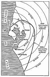
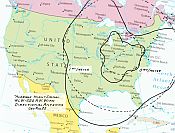
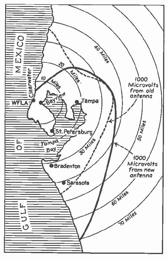
WFLA-WSUN
in Clearwater, Florida, built the
country’s first AM broadcast directional antenna in 1932. This coverage map shows
how the signal was
reduced to the north of the transmitter to protect a Milwaukee station,
while
improving the signal to the east, west and south.
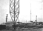
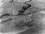
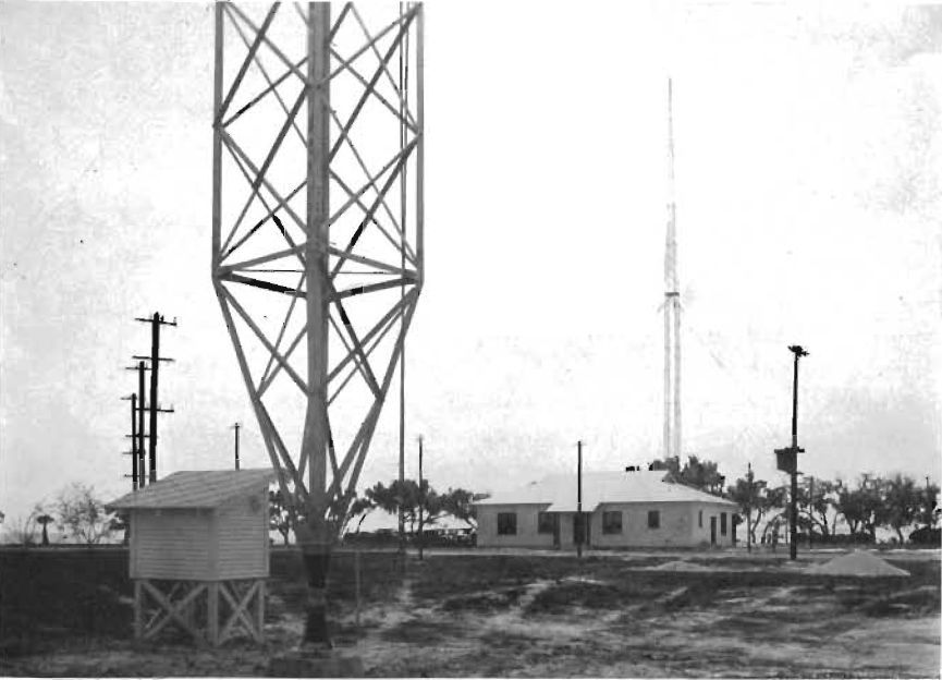
Here
is an early 1930’s
view of the WFLA-WSUN
antenna system, showing the station building and the two towers.
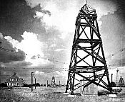
This
view shows the transmitter building and two
of the four towers that Westinghouse built in 1934 for KYW at
Whitemarsh,
twelve miles outside of Philadelphia.
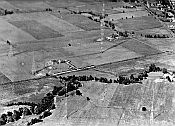
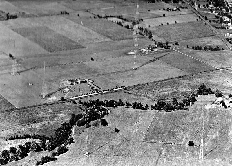
This
aerial view shows the WLW antenna complex
in Cincinnati in 1935. The
station’s
main 831 foot diamond-shaped Blaw-Knox tower is at the upper right. The two 326 foot towers in
the foreground
were the “suppressor antennas” designed to reduce WLW’s signal towards
Toronto
Another
view of the WLW towers, with the "supressor antennas" at the rear.
The two towers at the far right supported the antenna for
WLW's sister station, WSAI.

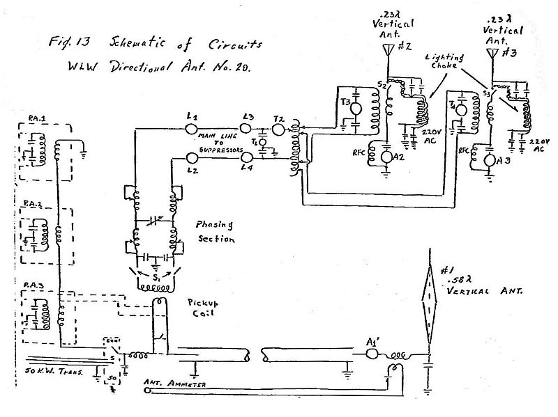
This sketch of the WLW
antenna configuration is taken from
documents created by the Crosley radio engineers.
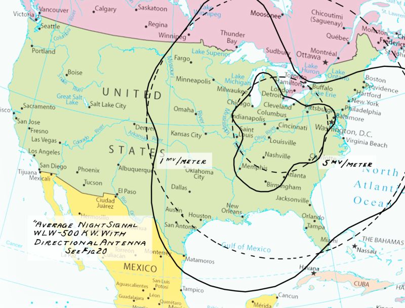
This
coverage map shows WLW’s
original 500 kW
non-directional nighttime coverage (dashed lines), and the coverage
achieved
with the directional antenna (solid lines).
The signal towards Toronto was greatly reduced to
protect station CFRB.
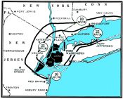
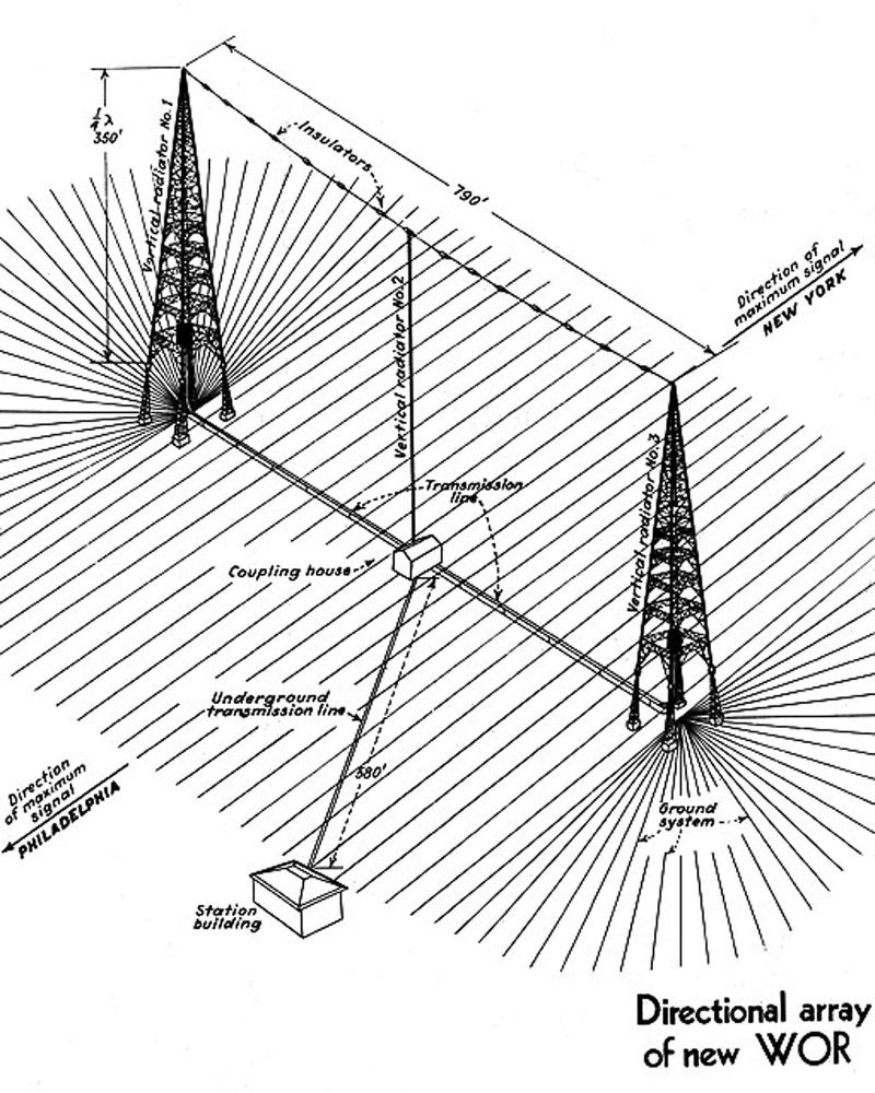
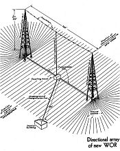 This drawing shows the configuration of the WOR
antenna system at Carteret, NJ, constructed in 1935.

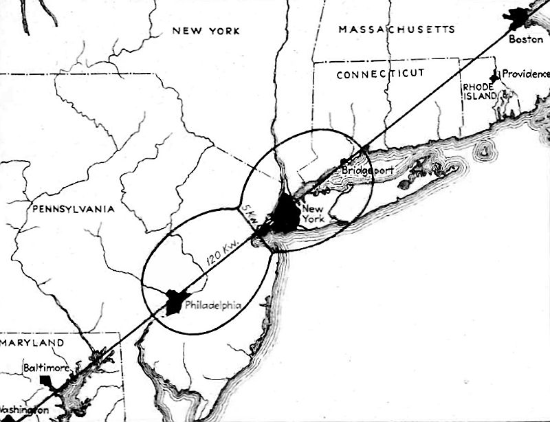
This map shows the theoretical WOR antenna
pattern, with an equivalent power of 120 kW in the main lobes and only 5 kW in
the nulls.
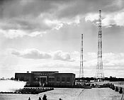
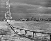
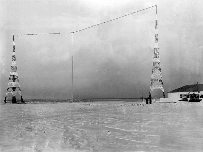
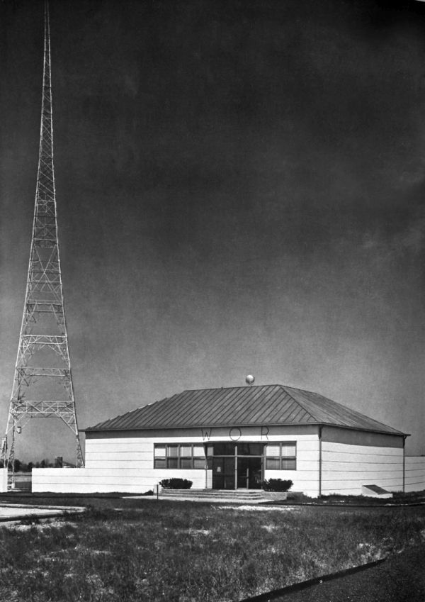
This 1935 photograph shows the WOR antenna system, with its
two 385-foot towers and transmitter building.
The drop-wire midway between the towers formed the third element of the
directional array.
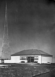
Here is a 1935 view of the WOR transmitter building.
 This was the transmitter building and antenna
system that NBC built for its key station WEAF in Bellmore, Long Island, in
1940. NBC decided to use a two-tower
directional system when its proposal for a single 740 foot tower was denied
because of aircraft restrictions.
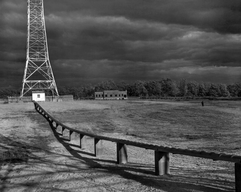
 This is a rear view of the WEAF antenna system,
showing the elevated raceway supporting the coaxial transmission line that
connected the two towers.

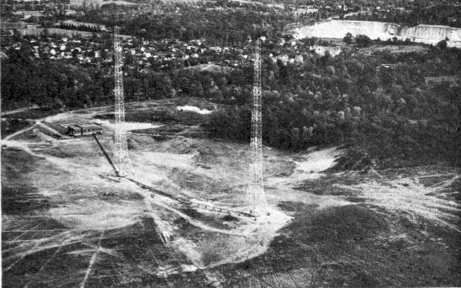
An aerial view of the WEAF site in 1942.
This coverage map shows the coverage that WEAF
achieved with its two-tower antenna system in Port Washington. Although most power was being radiated to the
west, there was still considerable signal in Long Island Sound to the east
because of its saltwater path.
|
|
In the early years
of AM radio broadcasting, all stations
utilized non-directional antennas.
Most
all of these were wire antennas suspended between towers or buildings. Interference, especially
at night was
severe. An
interfering signal of 5% or
less in signal strength was enough to disrupt reception of the desired
station,
and if the frequencies of the two stations were slightly separated,
there would
be a heterodyne beat note. As
a result,
only a few widely spaced stations could operate on each of the AM
broadcast
channels in the entire country at night. This
limited the number of stations that could
coexist to about 500 nationwide, with many of them sharing time on a
single
frequency.
As
antenna technologies were developed and improved in the
early 1930s, a few progressive stations began experimenting with
multi-element
directional arrays. It
offered two
attractive benefits: 1)
It could reduce
radiation towards other stations on the same or adjacent frequencies,
permitting more stations to share a frequency; 2) a broadcaster could
direct
more signal towards the desired coverage area, and away from wasted
areas such
as open water in the case of coastal stations.
WSUN-WFLA
The
first known use of a directional antenna was by a pair
of stations in Tampa/St. Petersburg, Florida.
In 1927, the Clearwater Chamber of Commerce acquired
station WGHB and changed
the call sign to WFLA. A
companion
station, WSUN, was operated by the St. Petersburg Chamber of Commerce. The two stations shared
the frequency of 900
kHz, broadcasting on alternate evenings to promote tourism and business
opportunities in their respective communities.
In reality, they operated with two station licenses
but there was only
one transmitter and one antenna.
In
1929, in a nationwide realignment of radio frequencies,
the Federal Radio Commission moved WFLA-WSUN to 620 kHz with a power of
2 kW
daytime and 1 kW nighttime. Immediately,
WTMJ in Milwaukee, Wisconsin, which also operated on 620 kHz, filed an
objection
with the radio commission, stating that its coverage was being impacted
by
interference from the Florida stations.
The commission responded by reducing WFLA-WSUN’s
power to 500 watts
daytime and 250 watts nighttime. This
news was distressing to the two chambers of commerce -- at those power
levels,
they would not have the nighttime coverage they needed to promote their
communities to the rest of the country.
WFLA-WSUN
contacted a Washington consulting engineer in
desperation to try and find a solution.
He was T. A. M. Craven, a former high-ranking naval
communications
officer who had resigned his commission in 1930 to go into private
practice as
a radio consulting engineer. Craven,
in
turn, called on Dr. Raymond Wilmotte, a British radio engineer who had
previously
experimented with radio direction-finding technologies in Europe. Wilmotte immigrated to the
USA in 1929 and
was working for the Boonton Aircraft Corporation.
Craven encouraged Wilmotte to leave his job
and open his own consulting practice.
Together, Craven and Wilmotte proposed the erection
of a directional
antenna that would reduce WFLA-WSUN’s radiation towards Milwaukee,
allowing the
stations to operate at a higher power level.
At first, the owners were skeptical of investing in
an untried
technology. Other
equally-respected
engineers believed that a working directional antenna was not possible
– they
thought the ionosphere would distort the signal’s directional
properties. But
Wilmotte was certain it would do the job,
and he proposed that he not be paid unless the project was a success. With such an assurance,
WFLA-WSUN gave him
the go-ahead.
Wilmotte
had two base-isolated vertical towers constructed.
Each was 200 feet high, separated by a
quarter wavelength on a bearing towards Milwaukee.
The towers were on opposite sides of what is
now the Courtney-Campbell Causeway in Clearwater.
The power from a new 5 kW Western Electric
transmitter was divided at the transmitter building and sent to each
tower via
open-wire transmission lines suspended from poles.
The
system was configured so that the two towers could be operated in-phase
during
the day and 90 degrees out of phase at night, creating a cardioid
pattern with
a sharp null towards Milwaukee.
The
first tests were conducted in May, 1932. There
were lots of trial-and-error adjustments
as they became educated in the unexpected complication of mutual
impedances
(the adjustment of one tower would change the tuning of the other
tower). Finally, a
precise adjustment was achieved
and the system worked even better than expected - so much so that the
government
engineer in Atlanta who was assigned to measure the signal strength
asked why
the station was off the air -- he could not hear the signal at all!
This
feat of engineering immediately caught the fascination
of the country’s broadcasters, and it boosted the careers of both
engineers. Broadcasting
Magazine foresaw
the significance of directional antenna technology when it wrote:
“The day when broadcasting
stations
will be enabled to predetermine their coverage and actually steer the
course of
their signals in given directions is envisioned.
…
Interference troubles, through the use of
this new directional radiating system, can be sharply curtailed, and at
the
same time make possible substantial increases in coverage in given
directions,
by putting the punch in the signals covering desired markets, and by
cutting
off propagation over useless areas.”
WSUN-WFLA
was allowed to increase its power, and operated
successfully from the two-tower system for the next 18 years. (The stations separated in
1941 when WFLA moved
to another frequency and both became full-time.)
A
few years later, T.A.M. Craven would become the FCC’s
Chief Engineer, and then was appointed by Franklin Roosevelt as an FCC
commissioner. He
held the position from
1937 to 1944, and was the only engineer ever to serve as a commissioner. For his part, Dr. Wilmotte
went on to patent
an anti-fading two-section vertical AM antenna. He
also helped create direction-finding
systems for airports, was involved with the development of radar, and
then
joined RCA to help develop the first communications satellites. In the 1970’s, the FCC
tapped him to develop a
high-performance UHF-TV tuner. He
died on
January 27, 2000, at the age of 98.
KYW PHILADELPHIA
In
1932, the Federal Radio Commission determined that the
clear-channel 1020 kHz frequency should be reassigned from the Midwest
to the
Mid-Atlantic States, in an effort to equalize the distribution of
clear-channel
frequencies across the country. That
1020 frequency was occupied by KYW in Chicago, owned by the
Westinghouse
Corporation. A
number of other
broadcasters applied to the FRC to take over the channel, but
Westinghouse ultimately
convinced the commission to allow it to move KYW from Chicago to
Philadelphia.
As
one of the foremost innovators in the art of radio
electronics, Westinghouse had the advantage of employing some of the
country’s
best radio engineers. They
set to work designing
an innovative directional antenna system for the new 10,000-watt KYW
transmitter site that was to be built at Whitemarsh, 12 miles north of
Philadelphia. The
array consisted of
four 200-foot steel poles that formed the four corners of a rectangle,
spaced
by a half wavelength on the long side of the rectangle and one-third
wavelength
on the short side. Each
pole was mounted
in an insulated cradle atop a 45-foot-tall lattice wooden base. The towers were fed by
individual transmission
lines from a phasing circuit that separately controlled the current and
phase of
each tower. For the
ground system,
55,000 feet of copper wire was formed into counterpoise cages suspended
horizontally ten feet off the ground around the base of each mast. The resulting figure eight
antenna pattern
was designed to maximize signals over Philadelphia and Allentown while
creating
a null towards New York City to protect WHN.
The raised tower bases were chosen to minimize
fading at the edges of
the KYW ground wave service area.
The
KYW transmitter building and its contents were equally
innovative. The
colonial-style stone building
was designed to blend in with the surrounding residential neighborhood. The custom-built
Westinghouse transmitter was
the first high-power rig to be completely operated from AC power,
eliminating
the use of troublesome DC motor-generators.
It incorporated nitrogen-filled capacitors, which
were more compact than
the air-dielectric capacitors then in common use.
All
transmitter components were built on open steel frames which were
completely
enclosed inside a room-within-a-room.
Interlocks on the doors prevented the operators from
entering while the
transmitter was in operation.
After
several weeks of testing from the new site after sign-off
in Chicago, Westinghouse made the official switch to Philadelphia on
December
3, 1934. In 1940,
KYW’s transmitter
power was increased to 50,000 watts, and the station moved to 1060 kHz
in the
1941 NARBA treaty nationwide frequency realignment.
The original antenna system operated until
1949, when it was replaced with the two 450 foot towers that are still
in use
today.
WLW CINCINNATI
Between
1934 and 1939, WLW in Cincinnati, Ohio, was the first
-- and only -- AM radio station in the United States ever authorized to
operate
with the remarkable transmitter power of 500 kW.
Upon being granted this coveted experimental
authority by the FCC, the Crosley Radio Corporation spent a half
million depression-era
dollars to construct the country’s most powerful radio facility. Broadcasting on WLW’s
clear-channel 700 kHz
frequency, the super-power transmitter at first only operated after
1:00 AM
using the experimental call sign W8XO, but after it proved reliable it
was
authorized to operate 24 hours a day using the WLW call sign.
The
existence of such a powerful signal on the radio
airwaves was certain to create interference.
And sure enough, in the summer of 1934 the FCC began
receiving
complaints from the Canadian government about interference to CFRB,
which
operated with 10 kW on 690 kHz in Toronto, 400 miles Northeast of
Cincinnati. “With
station WLW operating with 500
kilowatts”, read the official complaint, “the service area of the
Toronto station
was reduced to little more than the city of Toronto itself, and 50
miles out
the signals from Toronto were completely obliterated.”
WLW’s
experimental license needed to be reauthorized by the
FCC every three months, and WLW dutifully filed to renew the
authorization that
would expire in February, 1935. But
the
FCC’s response was the cancellation of WLW’s temporary authority,
stating that it
was obligated to comply with the international treaty that governed the
sharing
of the airwaves. WLW
would be allowed to
operate with 500 kW during the day, but would have to reduce its power
to 50 kW
at night. But
although the FCC had
closed the door, it left open a tantalizing window– the commission
would
approve 500 kW
nighttime operation “providing
such a radiating system is employed that the effective signal delivered
in the
area between Niagara Falls NY, Lockport NY and Lake Ontario does not
exceed the
effective signal in that area when operating with 50 kW.”
In
the 1930’s, the evening hours were radio’s “prime time”,
and WLW stood to lose a lot of advertising revenue if it couldn’t
operate its
super-power rig in the evenings, and so its engineers wasted no time in
coming
up with a solution to this unforeseen impediment.
After analyzing twenty different possible
solutions, the Crosley engineers chose to erect two 326 ft.
“suppressor”
antennas to reduce the signal intensity towards CFRB.
These two towers were constructed 1,850 feet
away from the main 831 ft. WLW tower, located directly in line on the
bearing
towards Toronto. The
height and location
of these towers were chosen to reduce the skywave signal towards
Toronto at an
angle of 20 degrees above the horizon.
By
April of 1935, WLW was conducting evening tests at 500 kW. Both the FCC and Canadian
engineers took
field measurements and were satisfied that the system was effectively
reducing
the signal towards Toronto to the 50 kW level.
Simultaneous
to the Canadian issue, the FCC received another
objection of possible WLW interference from WOR in New York. WOR was on 710 kHz, and was
concerned that the
proposed reduction in signal strength towards Toronto would result in
an
increase in signal towards WOR. In
response, WLW quickly sent a team of engineers to the East Coast to
make field
measurements. When
they proved to WOR
that there would be no objectionable interference, the WOR complaint
was
withdrawn and WLW resumed its full power evening broadcasts on May 8. It continued to broadcast
at this power level
as the industry and government argued over the benefits and evils of
super-power broadcasting. Finally,
under
pressure from Congress, the FCC set a ceiling of 50 kW on all AM
broadcasting
in the United States. WLW’s
days as a
super-power broadcaster came to an end on March 1, 1939.
WOR NEWARK NJ
Beginning
in 1922, the Bamberger Department Store had been
operating station WOR, which was licensed to the store’s headquarter
city of Newark,
NJ. (WOR was
relicensed to New York City
in 1941.) In 1935,
the station decided
to increase its power from 5 kW to 50 kW and moved its transmitter from
Kearny,
NJ, south to the village of Carteret.
A
new 35-acre site was built on the shores of the Arthur Kill channel,
across
from Staten Island.
The
WOR engineers, led by broadcast pioneer Jack Poppele,
wanted a directional antenna that would maximize the signal towards New
York
City to the Northeast and Philadelphia to the Southwest, while
minimizing radiation
over the mountains of Pennsylvania and the Atlantic Ocean. They contracted with the
AT&T subsidiary
Western Electric to build the new transmitter site, which in turn
employed their
engineers at the Bell Telephone Laboratories to design a directional
antenna
system.
The
WOR antenna consisted of two self-supporting 385 foot base-insulated
towers, which served as two elements of the directional array. They supported a taut
cable that stretched
790 feet between the tops of the towers, and a drop-wire conductor that
descended from this cable at the midway point served as the third
antenna
element. The ground
system consisted of
40 miles of number 8 buried copper wire.
This was one of the first radio installations to use
coaxial
transmission line, which was also buried.
The three elements of the antenna were fed in phase,
which produced a
broadside figure-eight array favoring New York City and Philadelphia.
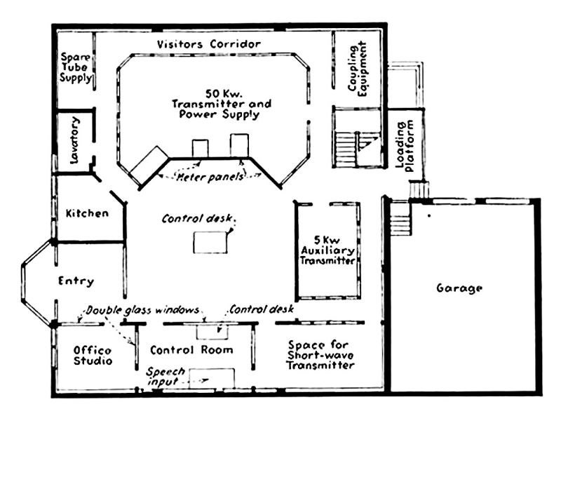
Inside
the spacious and windowless operations building, the
50,000 watt WOR transmitter was enclosed behind windows with a corridor
running
around it which allowed visitors to view the inner workings of the
system from
all angles. The
heat extracted from the
water-cooled transmitter tubes was used to heat the building.
On
March 4, 1935, President Franklin Delano Roosevelt threw
the ceremonial switch to launch the new WOR signal, and a gala day-long
program
was broadcast from Carnegie Hall to inaugurate the powerful transmitter. The Carteret site remained
in operation until
1968, when WOR moved to Lyndhurst, NJ.
MORE DIRECTIONAL
ANTENNAS
The
proven success of these directional antennas convinced
the FCC to accept the technology and create regulations for its use. This opened the floodgates
to applications
from dozens of other stations. In
1933,
WJSV in Washington, DC, (now WFED) installed a directional antenna to
reduce
interference at the Naval Laboratories on the Potomac River while also
increasing signal strength in Washington.
That same year, WKRC in Cincinnati installed a
directional system to decrease
interference to co-channel stations in Buffalo and St. Louis. In 1934, WMC in Memphis was
able to raise its
power from 1 kW to 2.5 kW while protecting WTAR in Norfolk, VA. Its system consisted of an
active vertical
antenna and a passive 185 foot reflector mast spaced a quarter-wave
distant on
the bearing towards Norfolk. A
dozen
other stations followed suit in 1935, including WINS in New York, KSD
in St.
Louis, and KWKH in Shreveport. In
1936, WWJ
in Detroit built a two-tower 5 kW directional system, and WBZ in Boston
used
two towers to reduce its signal over the Atlantic Ocean in 1939. In 1940, WEAF New York
(now WFAN) moved its
transmitter site 8 miles closer to New York – from Bellmore L. I. to
Port
Washington. Its
two-tower system was
designed to reduce the signal over the Atlantic Ocean and increase
power
towards the west.
By
1940, directional AM antennas were enough of a proven
technology that dozens of stations were using them to obtain power
increases or
fulltime operation. But
in the years
before computers, the current and phase parameters for each tower
needed to be
calculated by hand. This
was
mathematically complex and tedious process, and was understood by only
a
handful of expert radio engineers. The
few who had early knowledge of these systems, such as T.A.M. Craven,
were doing
brisk business designing new antenna systems.
By the start of World War II, there were 646 AM
radio stations on air in
America, and 39 of them were using directional antennas.
In
the early 1940s, Carl E. Smith (Cleveland Institute of Radio
Electronics) built an elaborate electro-mechanical device that could
calculate
and draw antenna patterns. He
published
a 238-page book in 1936 that gave the parameters for over 15,000
possible two-
and three-tower directional patterns.
The publication of this reference work greatly
simplified the design of
directional arrays and made it easier for their design and construction.
When the wartime
freeze on FCC applications was ended, hundreds of applications for new
AM stations were submitted, with many specifying the use of directional
antennas. Between 1940 and 1950, the number of AM stations in
the USA tripled to 2,000, and then increased again to 4,000 by
1970. This was all made possible by the use of directional
antenna technology. Today, the United States enjoys the
greatest number of AM stations of any country in the world, and there
are more directional antenna systems in the U.S. than all other
countries combined.
This article
originally appeared in the February, 2019, issue of "Spectrum Monitor"
Magazine.
REFERENCES:
Broadcasting Magazine:
- “Novel Plan Urged to Satisfy WTMJ”,
11-1-31
- “Power of WFLA-WSUN Cut to Improve
WTMJ”, 12-15-31
- “WTMJ Withdraws Appeal”, 1-1-32
- “WFLA-WSUN Experiment”, 4-1-32
- “A Directional Antenna of
Importance” (WFLA-WSUN), 7-1-32
- “High Efficiency Antenna Guides for
KYW”, 10-1-34
- “KYW to Transfer Operations”,
11-1-34
- “KYW Transplanted”, 12-1-34
- “WLW May Cut Power”, 1-1-35
- “Advances in Broadcast
Transmission”, 1-15-35
- “Court Delays WLW Power Cut”,
2-1-35
- “WLW Plans Directional Signal to
Meet Canadian Objections”, 3-1-35
- “WOR’s New Hour-glass Signal”,
3-1-35
- “WOR’s Protest Pending on 500 kW
Used by WLW”, 4-15-35
- “WLW Directional Signal is
Analyzed”, 5-1-35
- “WLW on 500 kW Nights with
Suppressor Antenna”, 5-15-35
- WOR full page advertisement, 7-1-35
- “Safety is Keynote at KYW”, 9-15-35
- Wilmotte obituary, 2-7-2000
“Radio
Engineering” Magazine:
- “Directional Antenna at WMC”, July,
1934
- “Directional Broadcasting at
WFLA-WSUN”, September 1932
- “Trends in Broadcast Engineering”
(WJSV and WKRC), July 1933
- “Directional Broadcasting”
(WFLA-WSUN) by Raymond M. Wilmotte, June 1934
“Electronics” Magazine:
- “Directive Antennae for Broadcast
Stations, December, 1932
- “The New WOR”, February, 1935
- “WEAF Port Washington”, September,
1940
Other Resources:
- Institute of Radio Engineers, “Transactions on
Broadcast
Transmission Systems”, February, 1957.
- Federal Communications Commission – Decision and
Order,
Crosley Radio Corporation, 1-25-35
- “RCA Broadcast News”, July 1932 -- “Directional
Broadcasting
at WFLA-WSUN”
- “Proceedings
of the
Institute of Radio Engineers”, Raymond M. Wilmotte biography
- “Radio Guide” Magazine, “Radio Roots Discovered at
Tampa
Bay” by Barry Mishkind, May 2003
- “Pick
Ups” newsletter
by WLW Technical Staff, 6-24-35 -- “The New WLW Directional Antenna”
- “NBC’s
New Building –
KYW’s New Studio”, booklet published by KYW about 1936
- Letter to Stuart B. Leland by E.H. Gager, KYW Plant
Manager,
2-6-35
- Directional Antennas, by Carl E.
Smith, E.E.,
Cleveland Institute of Radio Electronics, 1946
|


