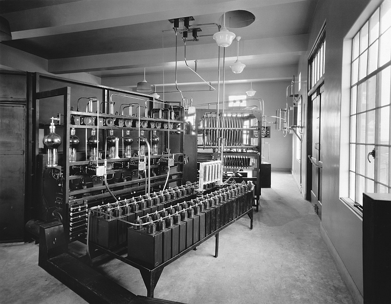
The driver section of the transmitter was located to
the left of the operator. It consisted of three cabinets. The left
cabinet was the power and control unit for the driver section. It
included the mercury vapor rectifiers for the 600 VDC and 3 KVDC
circuits. The center cabinet contained duplicate plug-in crystal
control oscillators, two intermediate RF power amplifiers (UX-860 and
UV-849), the speech amplifier (2 UV-211) and the modulator (2 UV-849).
Modulation took place in the UV-849 intermediat amplifier section. The
right cabinet is the 5 KW linear power amplifier, with 2 water-cooled
UV-863 tubes.
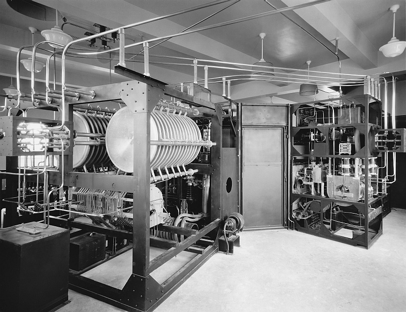
The 50 KW linear power amplifier was located on the
left-hand side of the center section, as viewed by the operator. It
utilized two UV-862 water-cooled tubes. To the immediate right of the
power amplifier was a monitor speaker and the main 50 KW rectifier
secction, which utilized six UV-857 mercury vapor rectifier tubes.
There was also a seventh tube which operated as a hot standby,capable
of replacing any of the other tubes at a moment's notice.
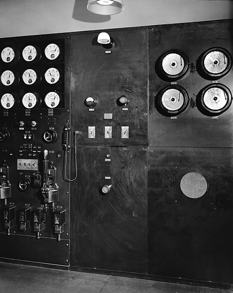
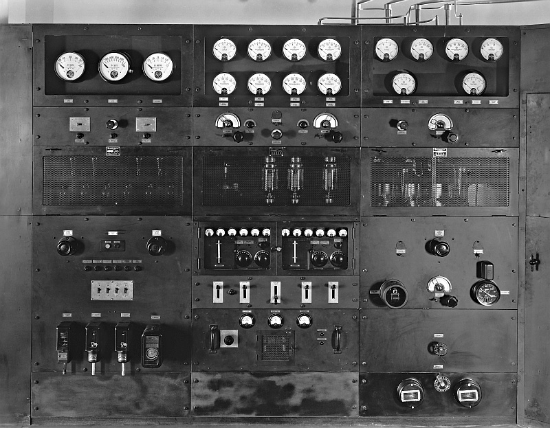
The panels to the right of the operator were the main control panel for the motor generators and water pump motors, as well as chart recording voltmeters and ammeters.
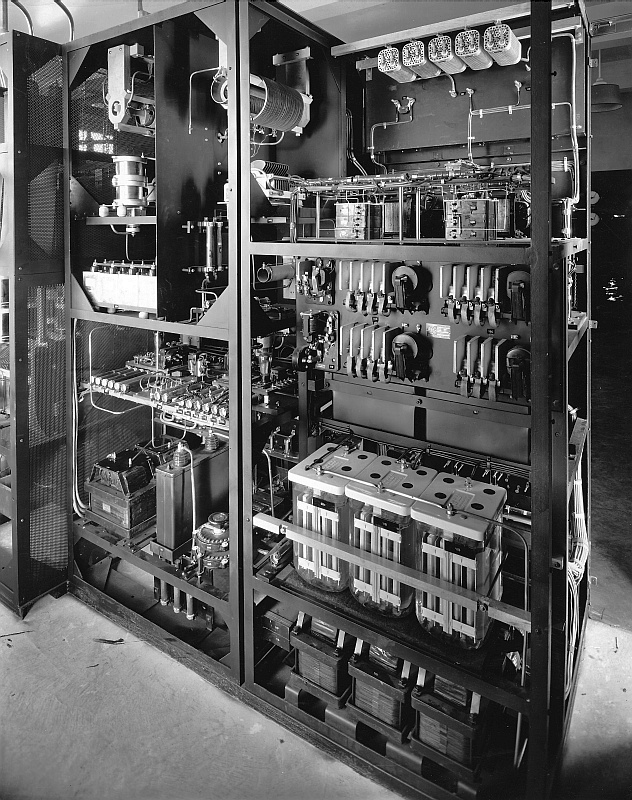
Rear views of the transmitter show the 5,000 watt driver stage (above), the output network (below, left) and the high voltage rectifier tubes (below, right).